5-5) Degassing by Helium Purging
Degassing Methods
Degassing by Helium Purging
Bubbling helium into the mobile phase causes the helium to dissolve and displace the dissolved air. As shown in Figure 27, the solubility of helium in respective solvents is generally low and, furthermore, is only slightly affected by temperature, as shown in Figure 28. Therefore, it helps to obtain a stable baseline with high sensitivity not only for UV and fluorescence detection, ( which is highly affected by dissolved oxygen) but also for refractometers as well. This method is referred to by terms such as helium purging, helium gas bubbling, or sparging.
However, even when mobile phase bottles are purged with helium, if the bottle is left open to the air, it can conversely cause extra baseline instability. The reason is because the gases in contact with the liquid always contain air, making it impossible to completely get rid of the air. In addition, changing the helium flow_rate causes the partial pressure of air to fluctuate as well, which in turn causes baseline drift. Therefore, when purging with helium, it is desirable to use a sealed pressurized system, possible.
Procedure
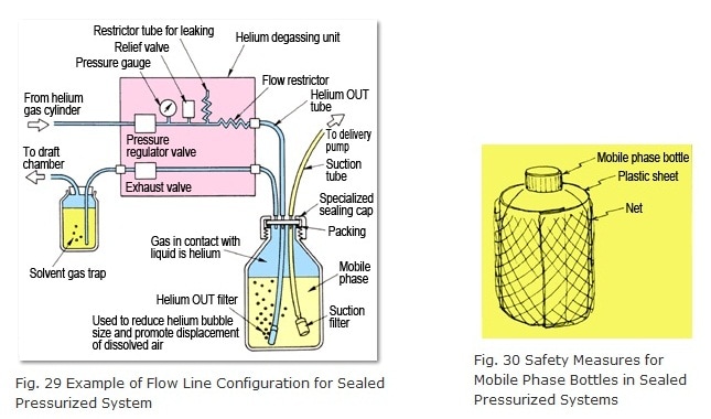
Sealed pressurized helium purging requires a flow line configuration like the one shown in Figure 29. One key point is to use a specialized sealed cap for the mobile phase bottle (included standard with DGU-10A and other models). First, initially raise the helium flow_rate (adjusting it via pressure to 0.02 to 0.05 MPa or 0.2 to 0.5 kgfcm-2, for example) for 10 to 30 minutes to purge the air from the mobile phase. Next, close the vent valve to slightly pressurize the gas in contact with the liquid. At this point, the mobile phase is ready for analysis. Thereafter, supply enough helium gas to compensate for the drop in mobile phase as it is delivered by the pump.
When analyses are finished, open the vent valve and set the pressure regulator valve to zero or shut the IN valve OFF, if provided. Since the helium is gradually escaping out the helium OUT tube (making it difficult for air to enter and creating vacuum pressure inside the tube), sometimes mobile phase can flow back out the helium OUT filter. If a restrictor tube for leaking is provided within the unit, this problem can be prevented by the backflow of air. If not available, introduce air by loosening the connection between the helium OUT tube and the unit.
The relief valve in the unit allows helium to escape to prevent excessive pressures inside the mobile phase bottle in the event the regulator valve fails or the pressure is set too high. Of course, to maximize safety, the mobile phase bottle should be wrapped in plastic sheet or a net (Figure 30). (A plastic sheet and net are included standard with DGU-10A models.)
Solvent gas traps are used to prevent volatile solvent vapors from diffusing into the room. However, for helium purging systems that are not sealed and pressurized, they can be also useful for keeping the gas in contact with the liquid at a nearly constant pressure.
Advantages
- Demonstrates the best degassing capacity.
- Degassing capacity does not depend on solvent delivery flowrate.

Disadvantages
- Requires a helium gas cylinder, regulator, and gas lines.
- Unless a sealed pressurized system is used, it may not be possible to maintain a stable baseline. Therefore, there are restrictions on the size and shape of the mobile phase bottle.
- Degassing mobile phases that contain volatile solvents can change the composition of the solvent. (Changes in composition are unlikely to occur once the system has stabilized using a sealed pressurized system.)
Applications
- High-sensitivity analysis for UV and all other detection methods (given a sealed pressurized system). (For open systems, helium purging is applicable for high-sensitivity analysis using fluorescence, electric conductivity, or electrochemical detection.)
- Analysis using low-pressure or high-pressure gradient mixing (high-precision analysis is possible if single solvents are placed in individual mobile phase bottles).

|
Note: |
This page is a partially revised html version of LCtalk Special Issue 5 (1991). |


